


Hand-Eye Coordination

The goal of this project was to demonstrate a system incorporating so called hand-eye coordination - the coordination between a camera and robot arm. The idea was to arbitrarily place a set of letters on the table, and provided the camera is overlooking them, the robot arm should pick up and order the letters the user has entered. The position and orientation of the letters is completely arbitrary as long as they are within the robot arm workspace and camera view. Also, it is assumed that the letters are face up with no overlap. There are two main components of the project: the computer vision and image processing component and the robot manipulation component. Here we present the first component, which involves camera calibration, letter recognition as well as the determination of the letter position and orientation relative to the robot base coordinate system. Once the letters are recognized and their positions and orientations are known the robot arm is directed to pick up and order selected letters.
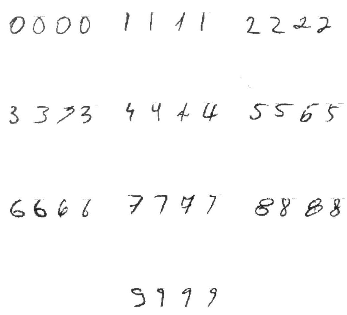
For this project we used wooden scrabble letters. First we constructed a database of letters by scanning the scrabble letters (Fig. 1) and then processing them to obtain a set of binary images containing only the letters (Fig. 2), i.e. with any additional features removed.
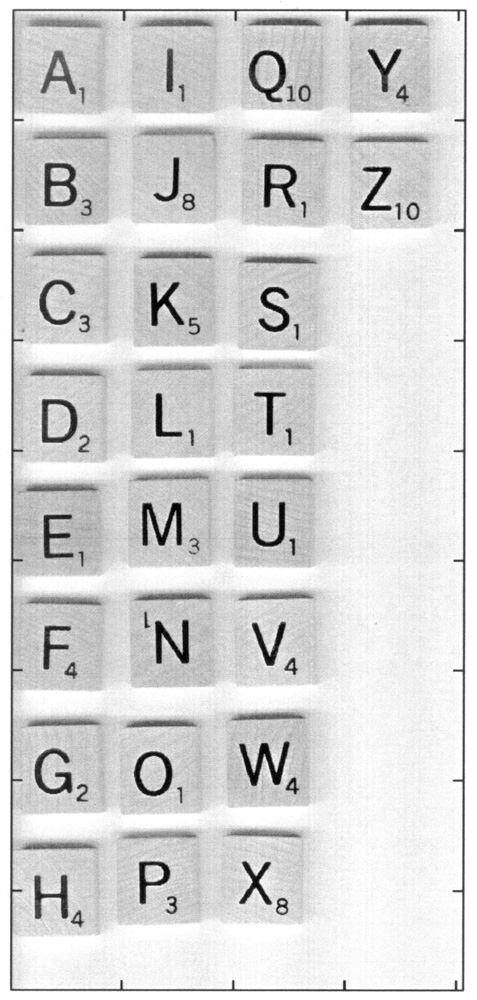
Figure 1: The scanned scrabble letters in addition to the letters contain number subscripts, wooden texture, and shadows.
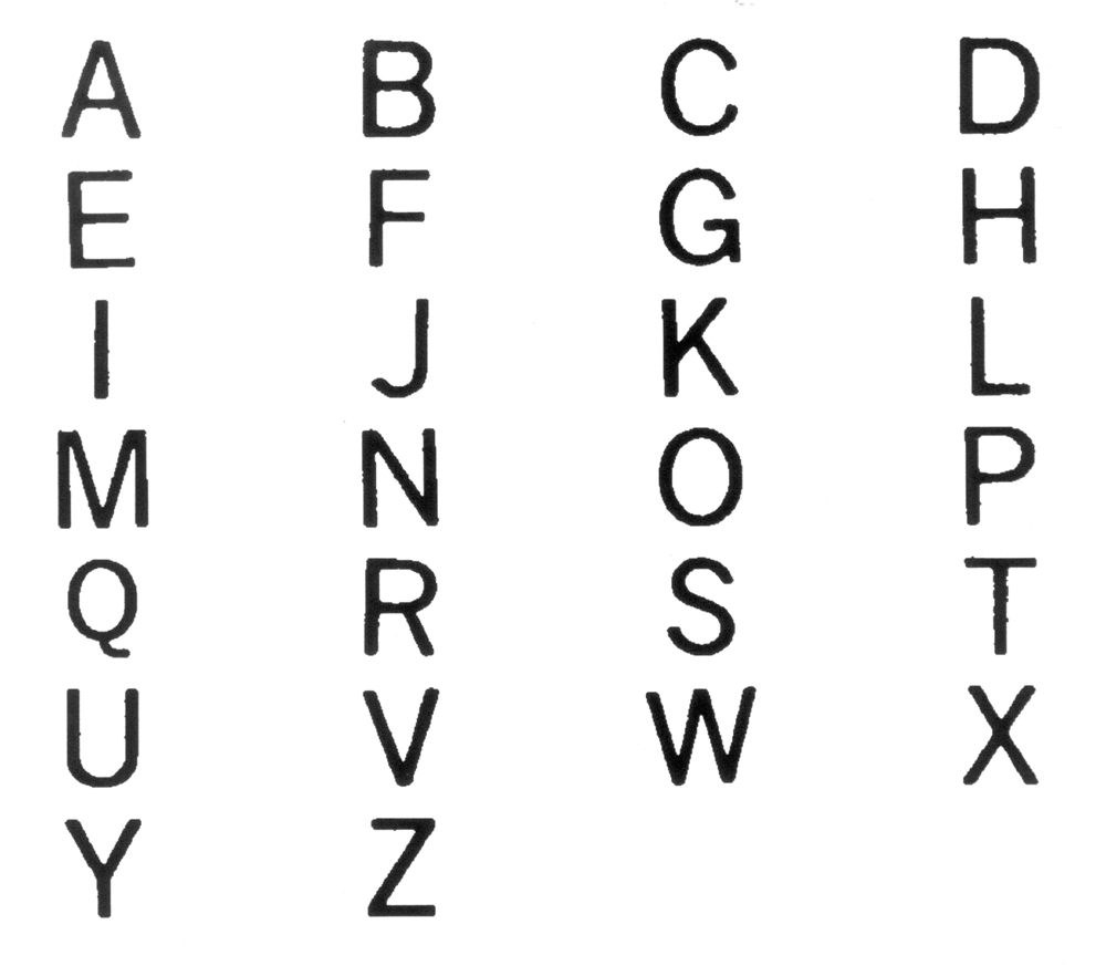
Figure 2: The processed database of letters is a set of binary images containing only the letters.
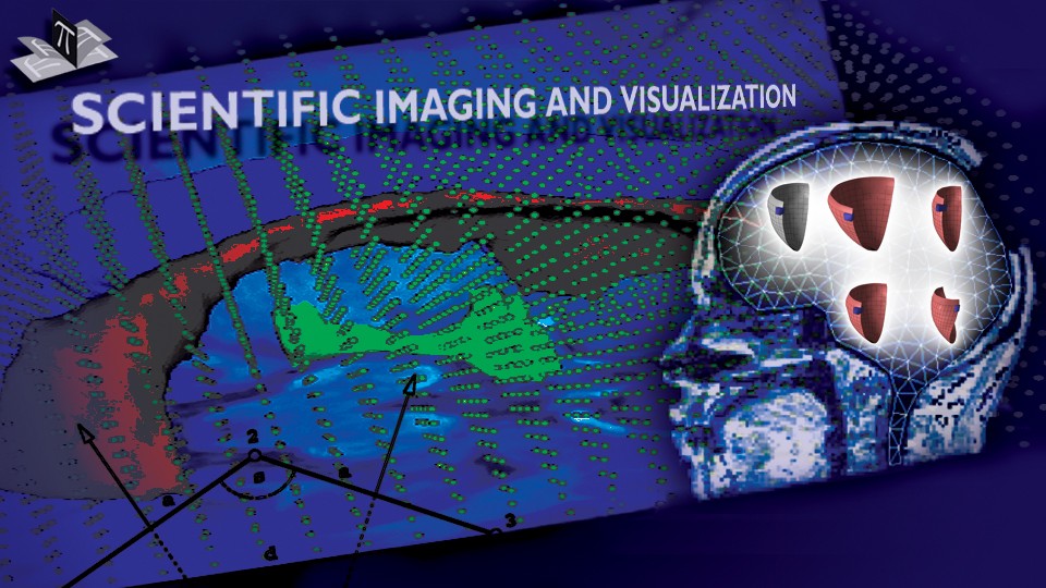
For the purposes of the camera calibration we drew on the table the "x" and "y" axis of a 2D coordinate system, which can be seen in Figs 3, 4, and 5. The 2D coordinate system was placed at a known position and with a known orientation relative to the robot base coordinate system. Since all the letters were in one plane (i.e. placed on the table), we were able to use a single camera for the system calibration and determination of the 3D letter position and orientation in the coordinate system of the robot base.
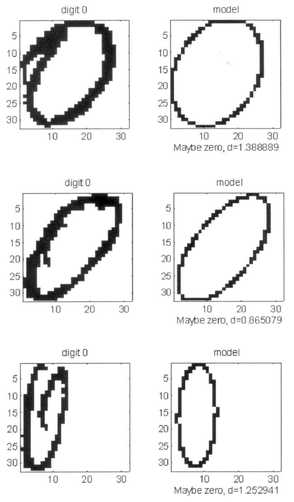
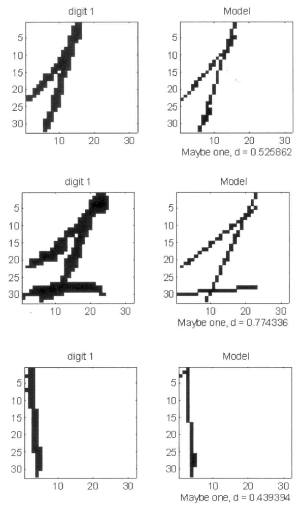
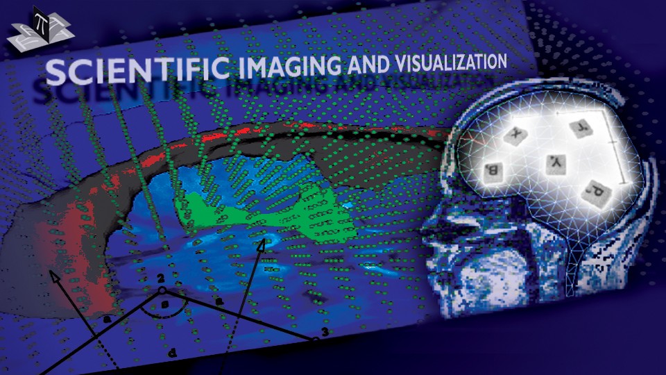
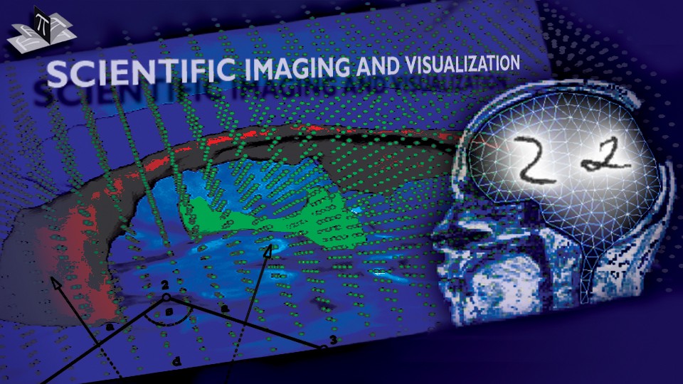
The first step in letter recognition was edge detection (Figs. 3, 4, and 5, top middle), from which we automatically removed the coordinate system and isolated letters. Isolated letters J, X, and P can be seen in the upper right corners of Figs. 3, 4, and 5, respectively. For each isolated letter we detected two top adjacent borders of the wooden block (Figs. 3-5, middle left). The two borders defined a local 2D coordinate system, which allowed us to back-project the letter (Figs. 3-5, middle center). To recognize the letter we tested the four possible orientations of the letter (Figs. 3-5, middle right and bottom row) against the database of letters. In each tested case the system correctly recognized the letter.

Figure 3: Steps of the automated letter recognition. A capture of randomly scattered letters together with the 2D coordinate system is shown in the top right, while the corresponding edge image is shown in the top middle. Isolated letter J is shown in the top right and its edge image with overlaid two top adjacent borders is shown in the middle left. The back-projected letter is shown in the middle center and its binary version in four possible orientations is shown in the middle right and bottom row. The four orientations were compared to the database of letters. The upright J, shown in the bottom center, had the smallest distance to letter J from the database and it was smaller than the distance of any of the four orientations to any of the letters from the database, which resulted in the correct letter recognition.
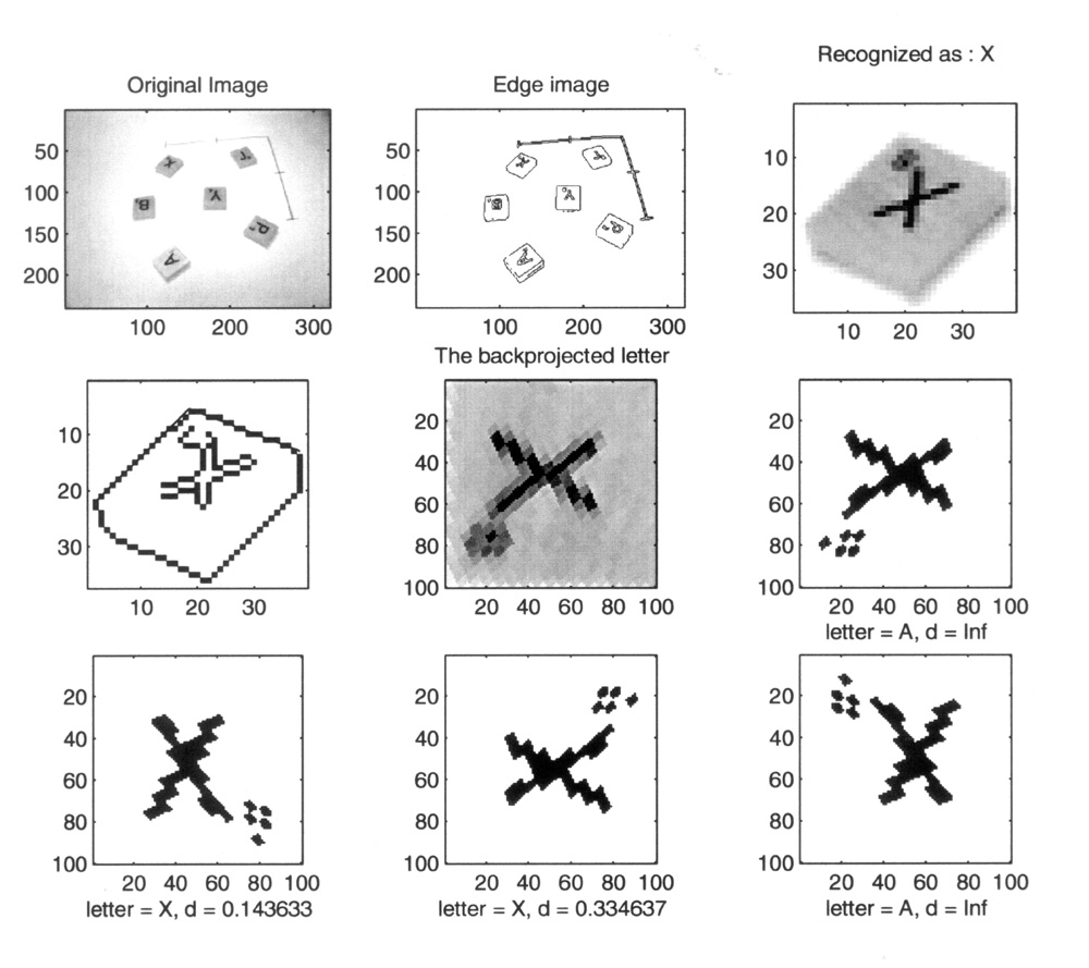
Figure 4: Steps of the automated letter recognition. A capture of randomly scattered letters together with the 2D coordinate system is shown in the top right, while the corresponding edge image is shown in the top middle. Isolated letter X is shown in the top right and its edge image with overlaid two top adjacent borders is shown in the middle left. The back-projected letter is shown in the middle center and its binary version in four possible orientations is shown in the middle right and bottom row. The four orientations were compared to the database of letters. The upright X, shown in the bottom left, had the smallest distance to letter X from the database and it was smaller than the distance of any of the four orientations to any of the letters from the database, which resulted in the correct letter recognition.
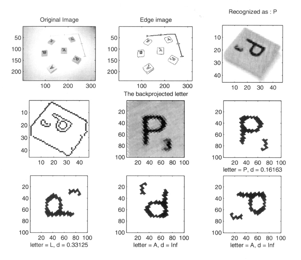
Figure 5: Steps of the automated letter recognition. A capture of randomly scattered letters together with the 2D coordinate system is shown in the top right, while the corresponding edge image is shown in the top middle. Isolated letter P is shown in the top right and its edge image with overlaid two top adjacent borders is shown in the middle left. The back-projected letter is shown in the middle center and its binary version in four possible orientations is shown in the middle right and bottom row. The four orientations were compared to the database of letters. The upright P, shown in the middle right, had the smallest distance to letter P from the database and it was smaller than the distance of any of the four orientations to any of the letters from the database, which resulted in the correct letter recognition.
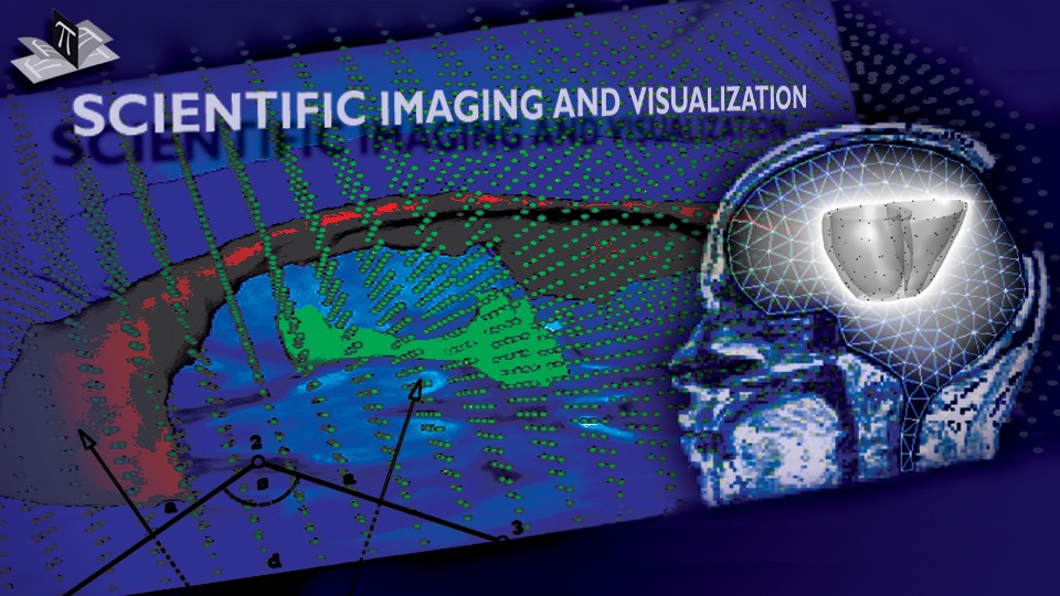
The 2D coordinate system (shown in Figs. 3, 4, and 5) was automatically detected and processed to determine its origin, orientation of the two axes and their unit steps (indicated by tick-marks; each axis had two tick-mars). Since the 2D coordinate system had known unit steps, position and orientation relative to the coordinate system of the robot base, and since all the letters were placed on the table, for any given point in the camera image we were able to compute its 3D coordinate in the robot base coordinate system. The 2D coordinate system with superimposed grid is shown in Fig. 6.
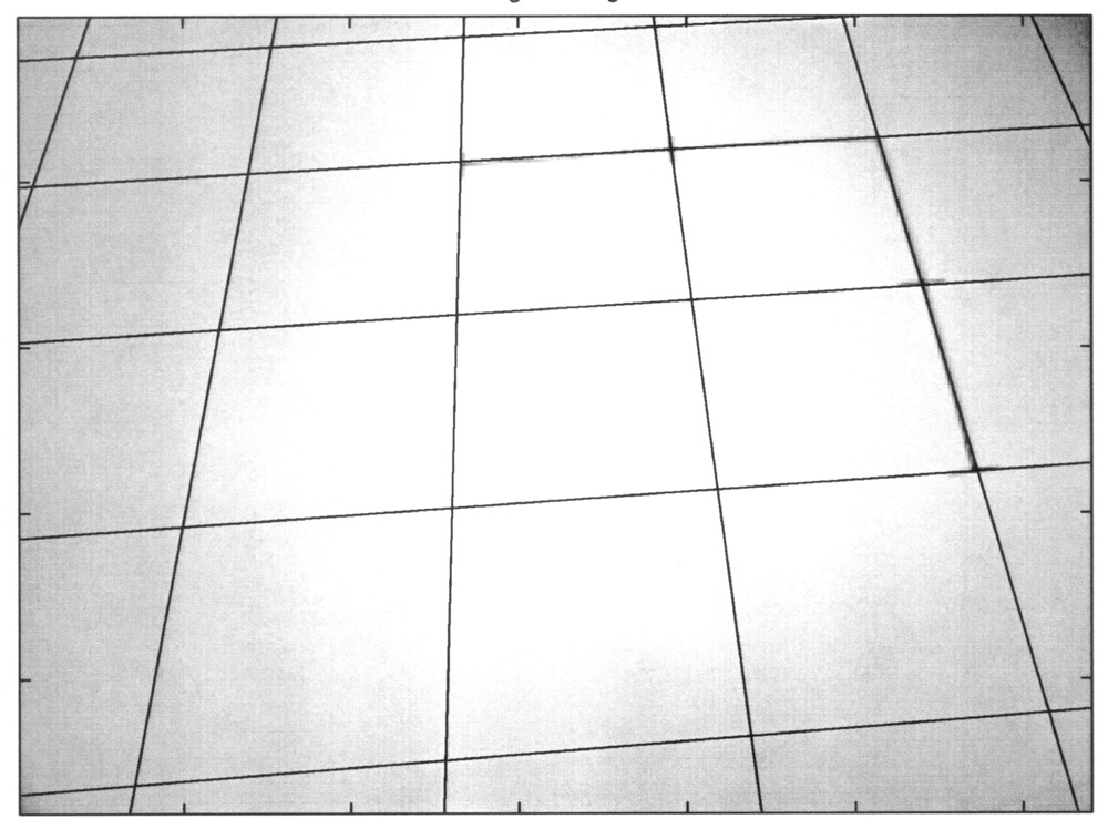
Figure 6: The 2D coordinate system with superimposed grid. The 2D coordinate system is barely visible since the grid lines overlap it. Note that the grid lines pass through the tick-marks of the "x" and "y" axes of the 2D coordinate system.
Once the letters were recognized and their positions and orientations determined in the robot base coordinate system, the robot arm was directed to pick up and order the letters forming user specified words. For this experiment we used a Connectix Quickcam with 320 x 240 pixels, and Mitsubishi Move Master EX (model RV-M1) robot arm with five revolute joints.