


Myocardial Surface Mesh Generation

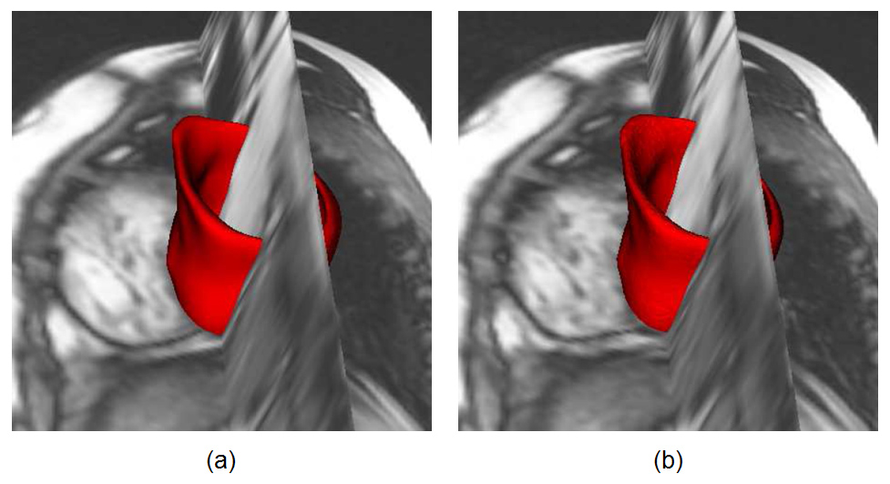
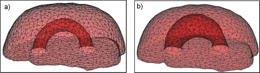
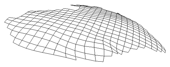
Due to a trade-off between spatio-temporal resolution and signal-to-noise ratio cardiac MR images typically have strongly anisotropic voxels. If such image are segmented and meshed, the resulting meshes usually have irregular triangles and pronounced terracing artifacts, none of which is desirable. An example of these effects can be seen in Fig. 1, where the marching cubes methods was used to generate the left ventricular endocardial surface from a cardiac MRI scan.
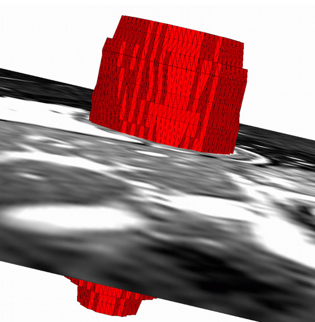
Figure 1: A left ventricular surface model generated by applying the marching cubes algorithm to a segmented cardiac MR image with 1.44 mm in-plane resolution and 8 mm slice thickness. The surface has pronounced terracing artifacts and irregular triangles. The figure is from [1] and it is used with permission; Copyright © 2009 Hindawi Publishing Corporation; All rights reserved.
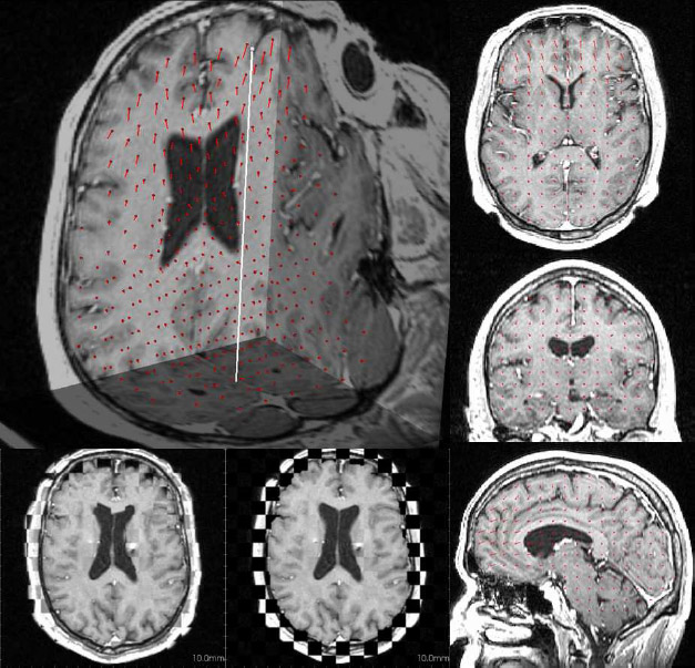
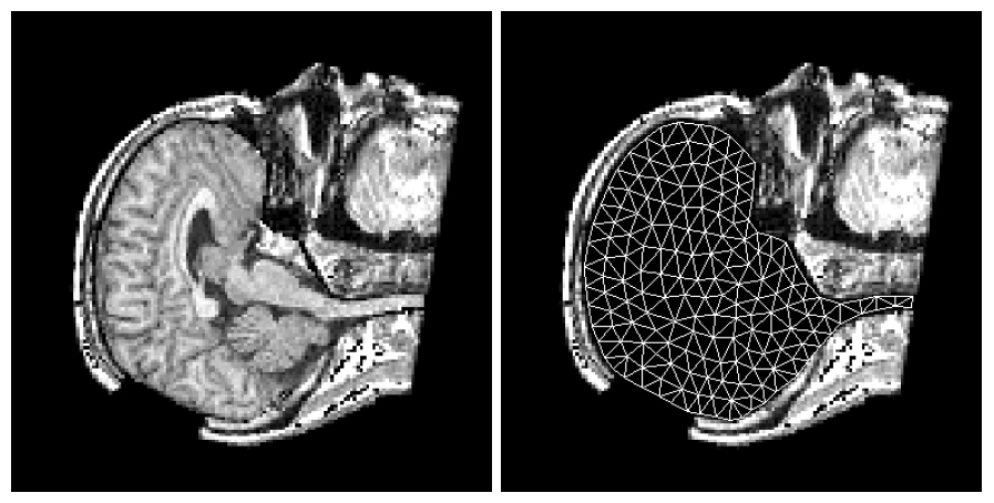
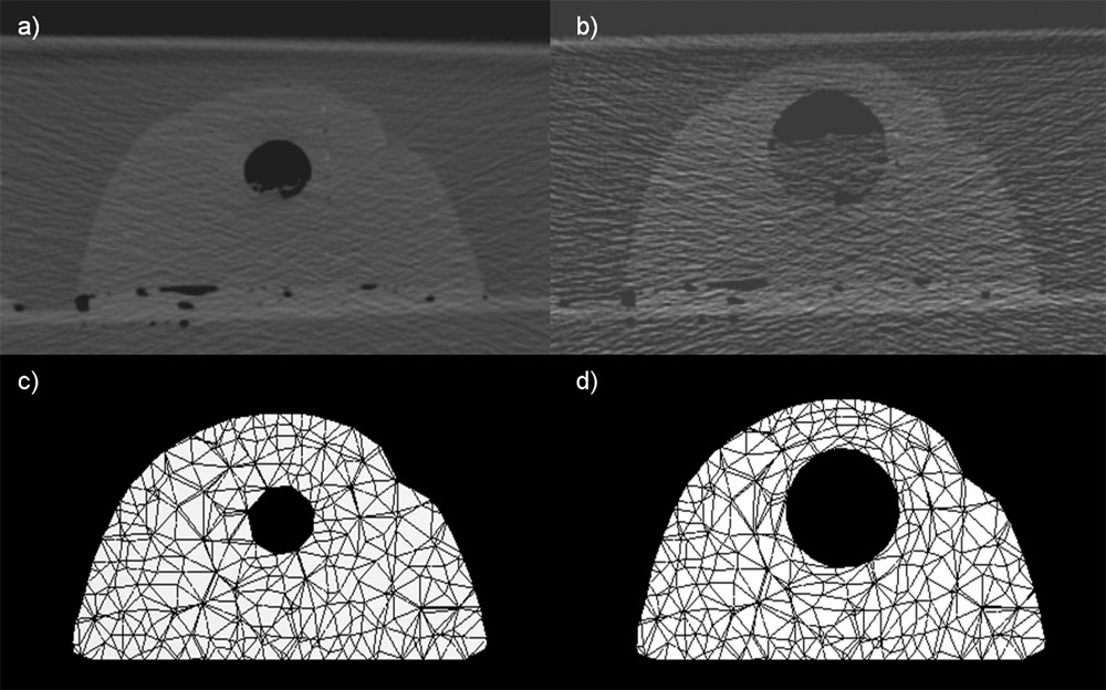
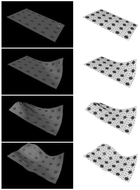
To address the above problems we have developed a novel method for the generation of myocardial wall surface meshes from segmented 3D MR images. The method maps a premeshed sphere to the surface of the segmented object. The mapping is defined by the gradient field of the solution of the Laplace equation between the sphere and the surface of the object. The steps of the method are illustrated in Fig. 2 and method details are given in [1].
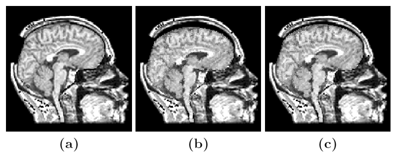
Figure 2: Mesh generation summary. The input image (a) is segmented into the object and background, resulting in a binary image (b). A sphere enclosing the object is centered at the object barycenter (c). The sphere is uniformly sampled with the number of points equal to the number of singularities. The binary image is resampled with isotropic voxels and the Laplace equation is numerically solved between the sphere (boundary condition of 0) and the object (boundary condition of 1). The solution of the Laplace equation is encoded in the gray levels in (c) and (d). The binary object is eroded, and the points are propagated from the sphere to the eroded object in the direction of the gradient of the Laplace equation solution to define the singularity locations, shown as red squares in (d) and (e). Boundary points, specified as midpoints for each pair of neighboring voxel, where one voxel is in the object and the other is in the background, are shown as red dots in (e). The singularity locations as well as the boundary points are used to specify the analytic solution of the Laplace equation. The boundary points are propagated in the negative gradient direction of the solution of the Laplace equation from the object boundary to the sphere (f). Their values of the underlying solution of the Laplace equation are interpolated at the sphere to the define the stopping function. The number of degrees of freedom of the stopping function is defined by the number of control points, which are shown as blue circles in (g). An approximately uniform mesh is generated on the sphere. The vertices of the mesh on the sphere, shown as black crosses in (g), are propagated from the sphere in the direction of the gradient of the solution of the Laplace equation until the value of the underlying solution of the Laplace equation is equal to the corresponding value of the stopping function. The propagated mesh nodes define the final mesh, shown in (h). Figures (a)-(h) are two dimensional for illustration purposes, while the method is three dimensional. The figure is from [1] and it is used with permission; Copyright © 2009 Hindawi Publishing Corporation; All rights reserved.
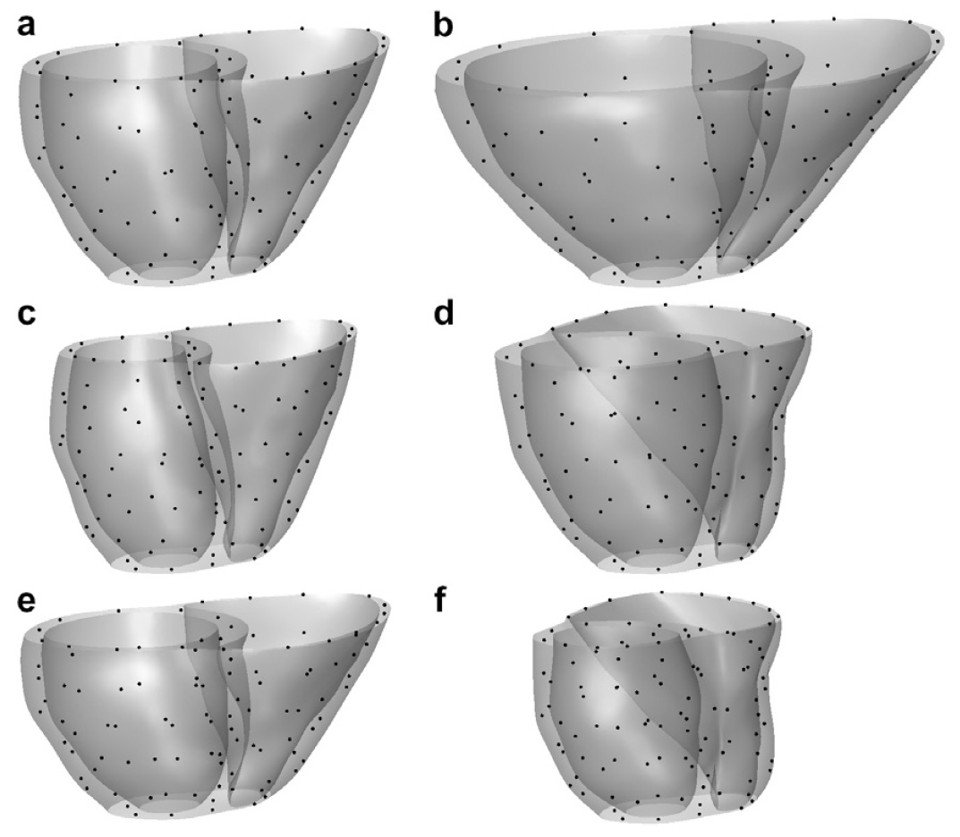
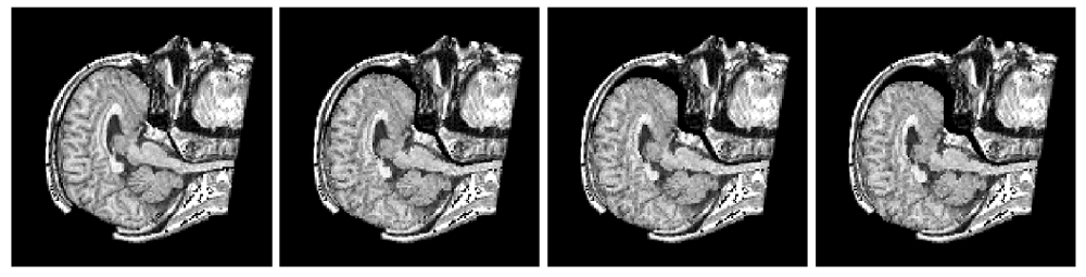
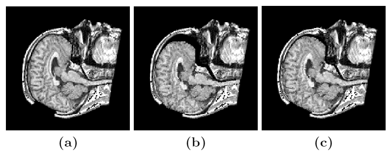
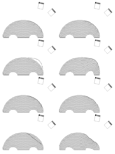
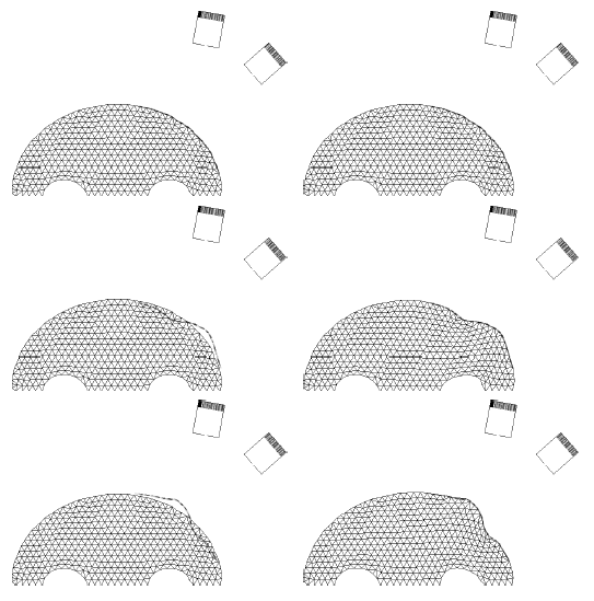
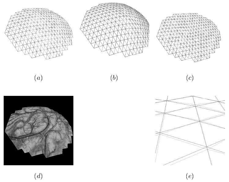
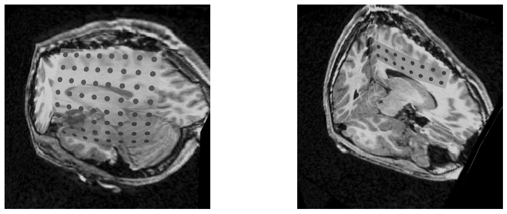
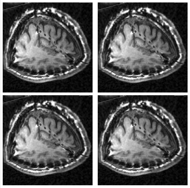
The method allows for the direct control of the number of mesh vertices and triangles (the two are directly related for closed surfaces). This is illustrated in Fig. 3 for the case of right ventricular endocardial surface, where the number of mesh vertices was varied from 200 to 5000.
Figure 3: Each column shows a mesh on the sphere and the corresponding right ventricular mesh obtained by propagating the mesh from the sphere to the right ventricular surface. The numbers of mesh vertices are 200 for (a) and (e), 500 for (b) and (f), 1000 for (c) and (g), and 5000 for (d) and (h). The figure is from [1] and it is used with permission; Copyright © 2009 Hindawi Publishing Corporation. All rights reserved.
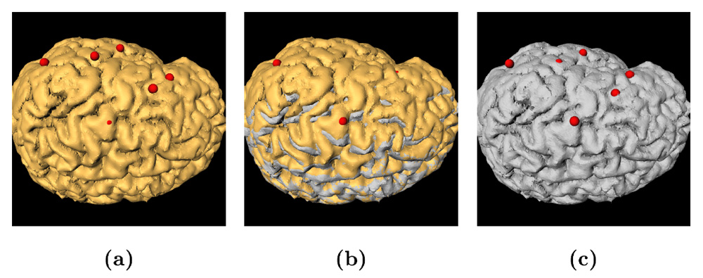
The same algorithm can be used to generate surface meshes of the epicardium and endocardium of the four cardiac chambers. The generated meshes are smooth despite the strong voxel anisotropy, which is not the case for the marching cubes and related methods. While the proposed method generates more regular mesh triangles than the marching cubes and allows for a complete control of the number of triangles, the generated meshes are still close to the ones obtained by the marching cubes. The method was tested on 3D short-axis cardiac MR images with strongly anisotropic voxels in the long-axis direction. For the five tested subjects, the average in-slice distance between the meshes generated by the proposed method and by the marching cubes was 0.4 mm.
References:
[1] Skrinjar, O., Bistoquet, A., "Generation of Myocardial Wall Surface Meshes from Segmented MRI", International Journal of Biomedical Imaging, vol. 2009, Article ID 313517, 10 pages, 2009. DOI:10.1155/2009/313517. LINK PDF