


Left Ventricular Deformation Recovery from Cine MRI

We have developed a method for 3-D deformation recovery of the left ventricular (LV) wall from anatomical cine magnetic resonance images (MRI) [1, 2]. The method is based on a deformable model that is incompressible, a desired property since the myocardium has been shown to be nearly incompressible. The model is parameterized with its midsurface, which in turn is defined by interpolating midsurface nodes. The model midsurface mapping is illustrated in Fig. 1, while Fig. 2 demonstrates the types of deformation that the model can generate.
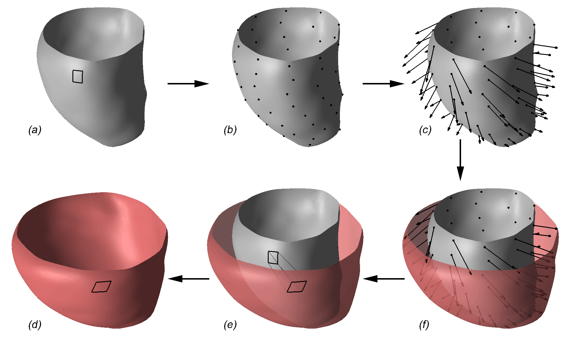
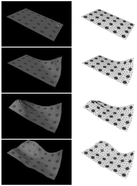
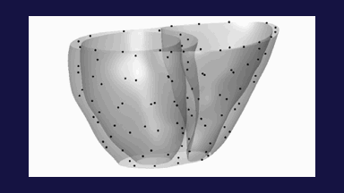
Figure 1: Mapping of the midsurface: (a) the LV wall midsurface of a normal subject in the reference configuration with an embedded curvilinear rectangle; (b) the midsurface in the reference configuration is obtained by interpolating nodes shown as black dots; (c) each node is assigned a displacement; (f) the node displacements are interpolated to obtain a continuous displacement function, which is then applied to the entire midsurface; (e) the displacement function is applied to the curvilinear rectangle; (d) the resulting midsurface in the current configuration with the curvilinear rectangle. The parameters of the midsurface mapping are the node displacements, which can be arbitrarily specified. For illustration purposes, the applied transformation in this figure is artificial and larger than real. It contains radial expansion, longitudinal shortening and a circumferential twist. It can be seen in (e) that the curvilinear rectangle moved outward (radial expansion), downward (longitudinal shortening), rotated to the right and slanted (circumferential twist). The midsurface in the reference configuration is rendered gray and in the current configuration it is rendered red. The figure is from [1] and it is used with permission; Copyright © 2007 IEEE; All rights reserved.
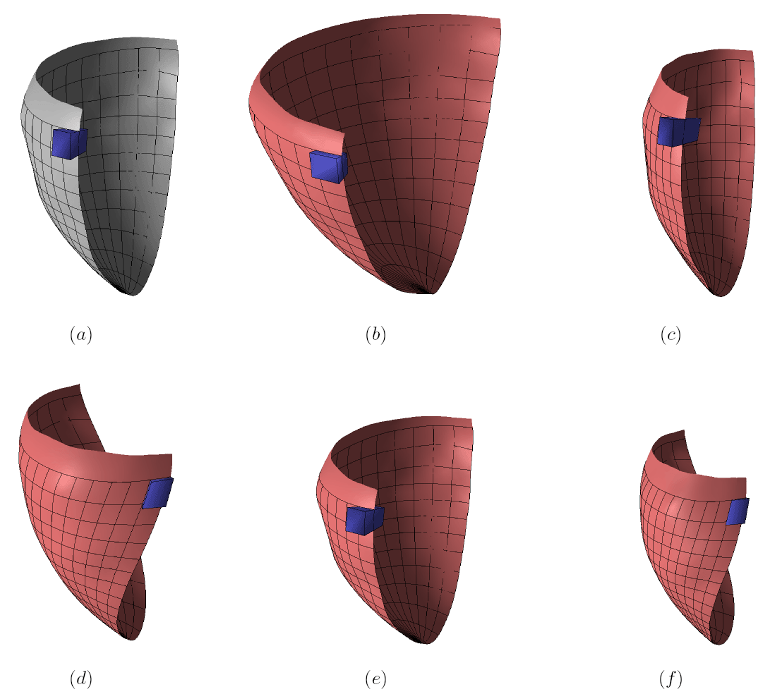
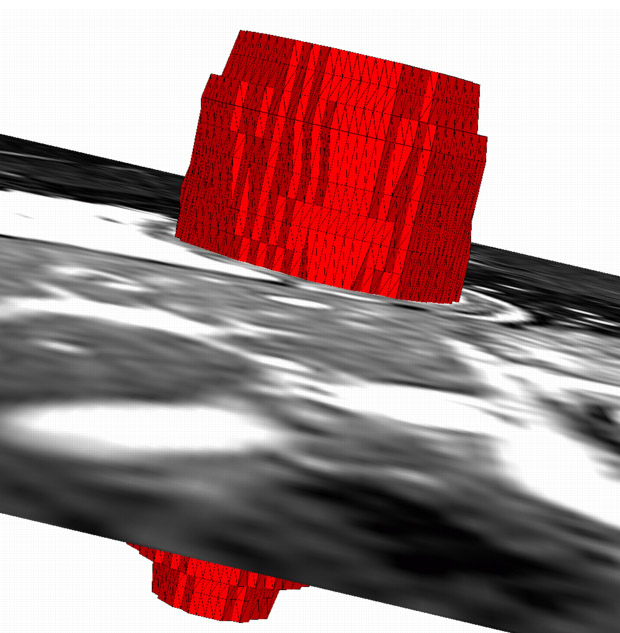
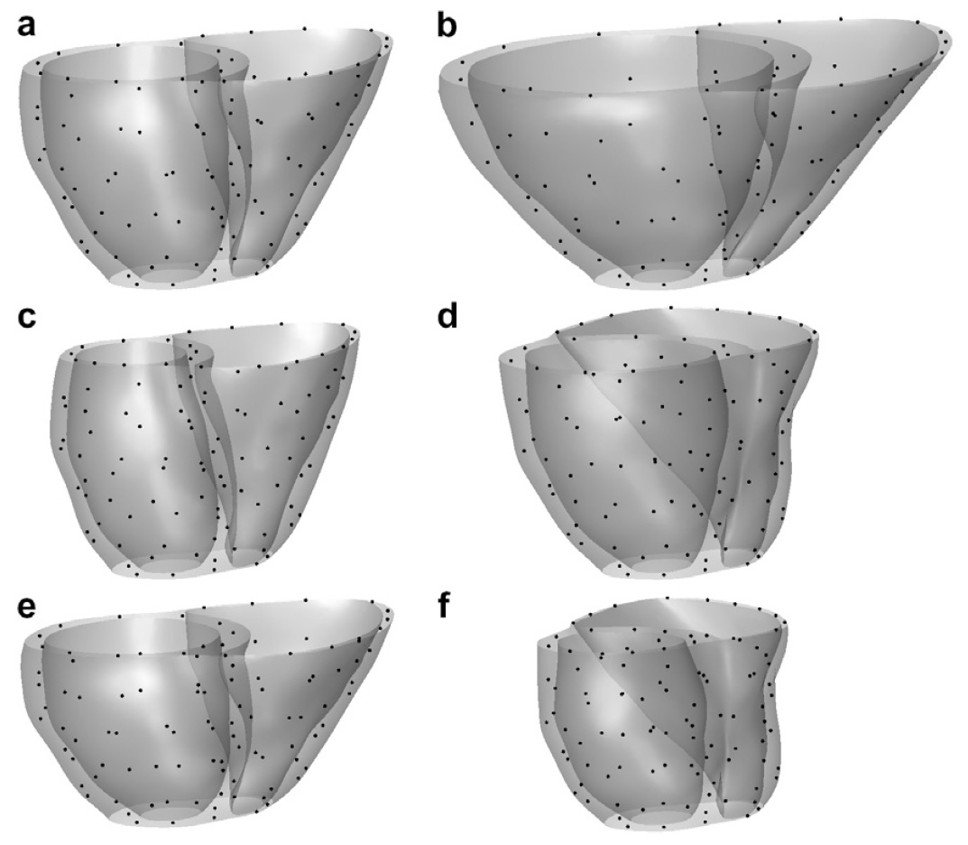
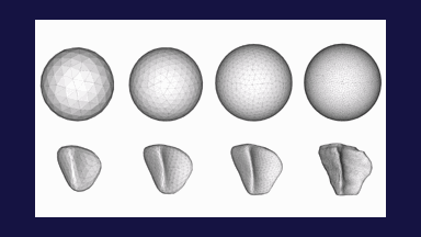
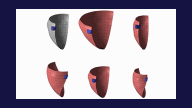
Figure 2: A half of the LV wall midsurface (gray) at ED of a healthy volunteer is shown in (a). The blue block represents a chunk of the LV wall. Artificial transformations are applied to the model to illustrate (b) radial expansion, (c) radial contraction, (d) circumferential twisting, (e) longitudinal shortening, and (f) combined radial contraction, circumferential twisting, and longitudinal shortening, which is a deformation pattern typical for ES. Note that the wall (blue block) thins in (b) and thickens in (c) and (e). While it cannot be seen due to the angle of viewing, the wall undergoes almost no change of the thickness in (d) and it thickens in (f). The thinning and thickening of the wall is a consequence of the model incompressibility. Also note the slanting of the blue block in (d) and (f), which is a consequence of the circumferential twisting. The curvilinear grid is shown to better visualize the deformation patterns. The figure is from [1] and it is used with permission; Copyright © 2007 IEEE; All rights reserved.
The LV wall needs to be segmented in an initial frame after which the method automatically determines the deformation everywhere in the LV wall throughout the cardiac cycle. The segmented LV wall in end diastole (ED) of a subject is shown as a surface model in Fig. 3a, while the deformed model corresponding to the end systolic (ES) image is shown in Fig. 3b. Cross sections of the LV surface model at midventricular and basal short axis MRI slices are shown in Fig. 4 over the cardiac cycle.
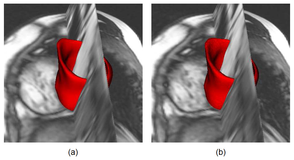
Figure 3: A 3D surface model of the left ventricular wall of a subject is shown together with a short axis slice and reconstructed long axis slice in ED (a). The recovered deformation of the ES was applied to the surface model, which is shown together with the same short axis slice and reconstructed long axis slice in ES (b). The figure is from [2] and it is used with permission; Copyright © 2006 IEEE; All rights reserved.
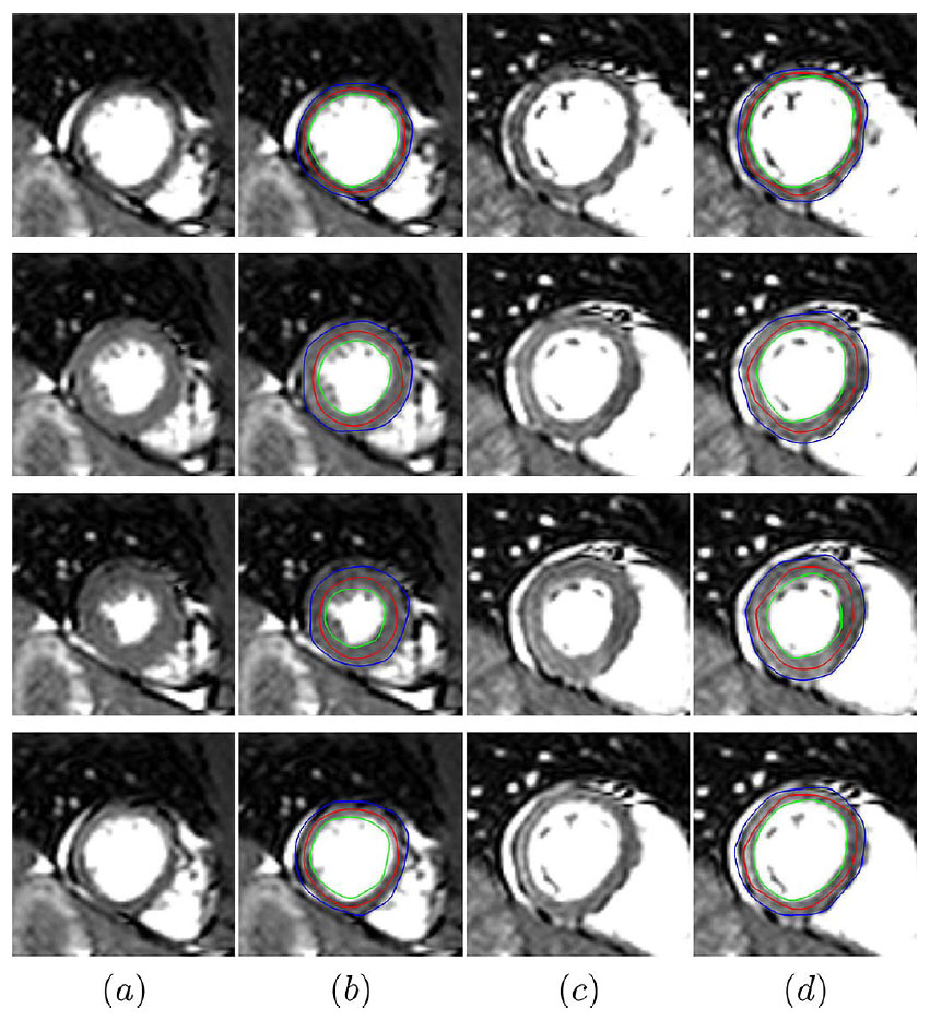
Figure 4: Recovered LV wall deformation for a normal subject over the cardiac cycle (first row: ED, third row: ES) is shown by means of the endocardial surface (green), midsurface (red), and epicardial surface (blue) contours: (a) a midventricular slice, (b) the same slice overlaid with the contours, (c) a basal slice, (d) the same slice overlaid with the contours. Synchronous thickening of the myocardium indicates normal cardiac function. The figure is from [1] and it is used with permission; Copyright © 2007 IEEE; All rights reserved.
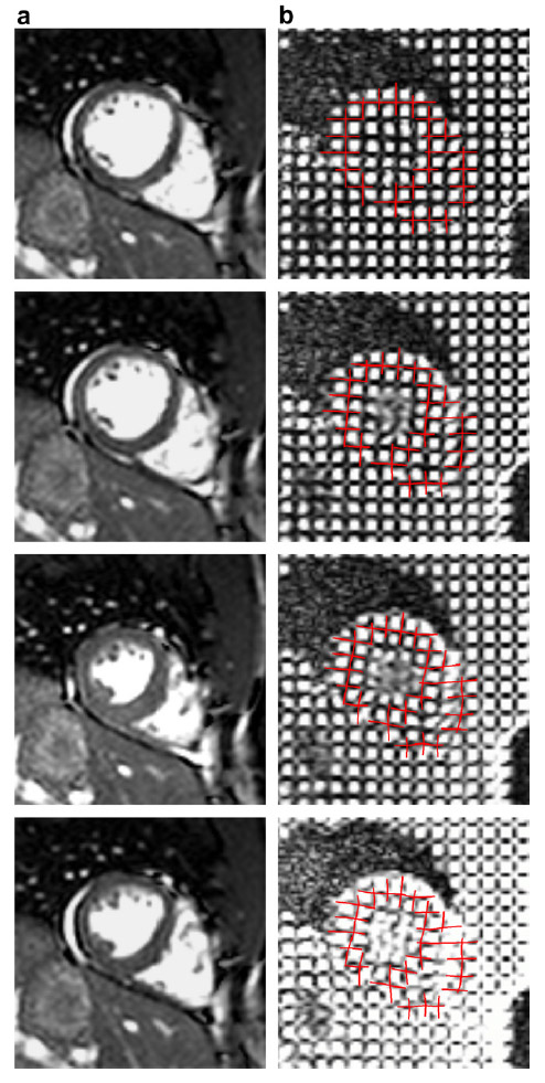
To validate the method, we compared the deformation recovered from a 3-D anatomical cine MRI to the myocardial displacement obtained from corresponding 3-D tagged cine MRI. The average distance between the model and manually determined intersections of perpendicular tag planes was 1.1 pixel. This is illustrated in Fig. 5.
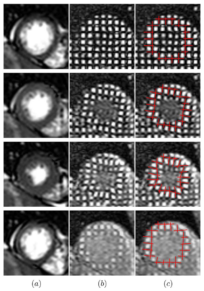
Figure 5: Midventricular short axis slice from the anatomical cine MRI scan is shown in (a) over the cardiac cycle (first row: ED, third row: ES). Corresponding slice in the tagged cine MRI scan is shown in (b). Slice from (b) is overlaid with virtual tag lines in (c). Virtual tag lines were generated by applying the deformation recovered from the anatomical scan to the manually positioned tag planes at ED. The figure is from [1] and it is used with permission; Copyright © 2007 IEEE; All rights reserved.
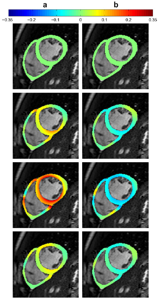
Once the 3D myocardial displacement field is recovered, one can directly compute myocardial strain. Fig. 6 shows radial and circumferential strain of a normal subject and a patient in a short axis slice over the cardiac cycle.
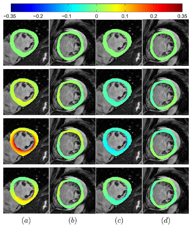
Figure 6: Color-coded Lagrangian strains for a normal subject and a patient are shown in a short axis slice over the cardiac cycle (first row: ED, third row: ES): (a) radial strain for the normal subject, (b) radial strain for the patient, (c) circumferential strain for the normal subject, (d) circumferential strain for the patient. Since the deformation is measured relative to ED, the strains in the ED frame are zero. Strains are shown over the ED frame image. Lower strain values in the patient indicate reduced cardiac contractility. In addition, the regional heterogeneity in strain distribution in the patient images indicates either dyssynchrony or ischemic myocardium. The figure is from [1] and it is used with permission; Copyright © 2007 IEEE; All rights reserved.
References:
[1] Bistoquet, A., Oshinski, J., Skrinjar, O., "Left Ventricular Deformation Recovery from Cine MRI Using an Incompressible Model", IEEE Transactions on Medical Imaging, 26(9): 1136-1153, September 2007. LINK
[2] Bistoquet, A., Parks, W. J., Skrinjar, O., "Cardiac Deformation Recovery using a 3D Incompressible Deformable Model", IEEE Workshop on Mathematical Methods in Biomedical Image Analysis, New York, NY, USA, June 2006. LINK